Dimensions in AutoCAD are the most important component when working with drawings. This is a complex object, which is perceived as a whole and consists of an extension and dimension line and the size itself. For a more understandable distribution, two main types should be distinguished: angular, which, respectively, provides information about the magnitude of the angle, and linear, characterizing length, width, height, thickness, and similar values.

It is necessary to take into account the fact that the application of dimensions, and in principle, all work with the drawing, is governed by the standards prescribed in "GOST 2.307 - 68". And these standards should not be neglected.
How to put dimensions
First you need to create the shape itself, in which you want to dimension.
Then expand the "Abstract" tab and click on the "Dimensions" section.
Now you need to select a view, for example, “Linear”.
At the bottom of the screen at the command prompt appears:

Using the mouse and the cursor, alternately specify the first and second points of the defined segment on the selected shape.
After the necessary points are determined, you will be asked to select the location of the dimension line:

After it turned out to indicate the locations of the values, press the Enter key to accept the entered data.
As an alternative, you can bypass the marking of points by a side and use the selection of a part of the drawing.
To do this, you will need to immediately press "Enter" on the first request, thus the function "Select object" will be applied.
Now it remains only to indicate by clicking part of the figure / drawing and retracting the cursor and clicking the mouse, to determine the location of the dimension line.
Additional options
These options have already been mentioned above, they appear on the first prompt on the command line, and their purpose is as follows:
- “Mtext” is the option that calls the editor. It allows you to change the already entered data or put additional characters in the form of "+" / "-" / "&", etc.
- “Text” - this option provides the ability to edit text directly from the command line, without involving and without calling the editor.
- "Angle" - is used to change the angle of rotation of the entered text.
- “Horizontal / Vertical” - to determine only the vertical or only the horizontal arrangement of values.
- “Rotated” - according to the same principle as the “Angle” option.
How to make a callout
In complex objects, drawings, there are situations in which there is simply no place to take a dimensional value, or it will simply be out of place due to the presence of many details.
It is for these purposes that the “Callout” option exists, which allows you to set the desired dimensional value beyond the selected object.
First of all, set up the appearance of the callouts, call the “Multileader Style Manager” for this, and then click on the “Edit” button to change the default style.
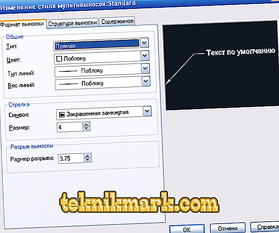
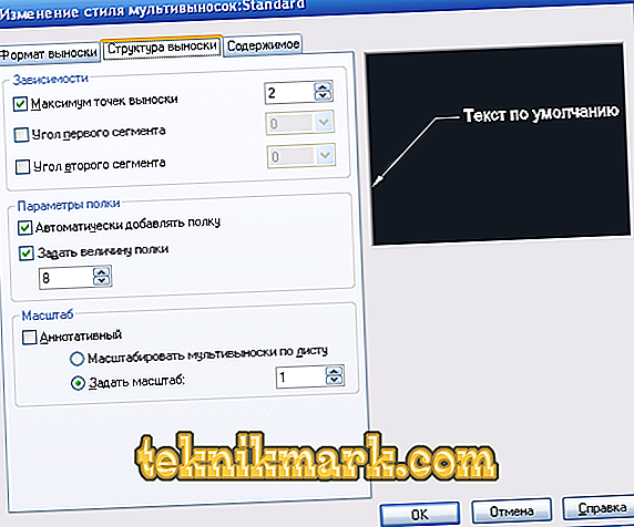
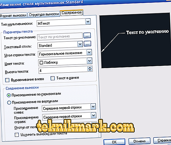
In the dialog box “Changes in styles of multileaders: Standart” there are three tabs:
- “Format” - you can choose the type of callouts: straight or spline, color, thickness and type of lines, as well as an arrow symbol.
- “Structure” - the size of the shelf acts as the main parameter.
- "Content" - is used to edit the text component (notes).


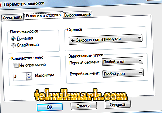
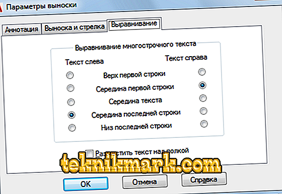
It is also worth paying attention to the “Leader parameters” dialog box, similarly to the one described above, 3 tabs are shown or provided, which define the following parameters:
- "Annotation". It is based on the definitions of the type of annotation, the Mtext mode and the choice of reuse.
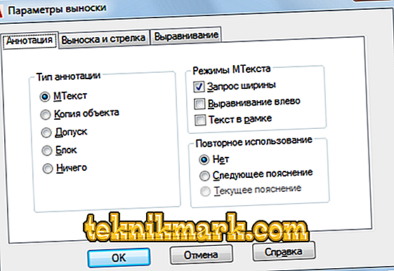
- "Callout and arrow". The appearance of the indicated leader lines, the appearance of the arrow, the number of points and the dependence of the angles.
- "Alignment." Specifies the position of the right and left text or the placement of text above the shelf.


Useful commands and variables
- “CMLEADERSTYLE” - to set the name of the current multileader style;
- "BRAZMER" - serves to apply values based on selected objects;
- “RZMDIAMETER” - setting the diameter of the arc or circle;
- "REZMORDINAT" - drawing ordinate dimensional values;
- "RZMRAZORVAT" - to restore or break the dimension lines that intersect others.
Many novice users are faced with the fact that the drawing has ceased to be displayed or the size was not visible at all. The reason is simple. The fact is that the necessary values are displayed, but by default the minimum size is set, which is simply not visible on the large drawing. The problem is solved by simply enlarging the object (by scrolling the mouse wheel) and / or by setting the external display in the dialog boxes described above.