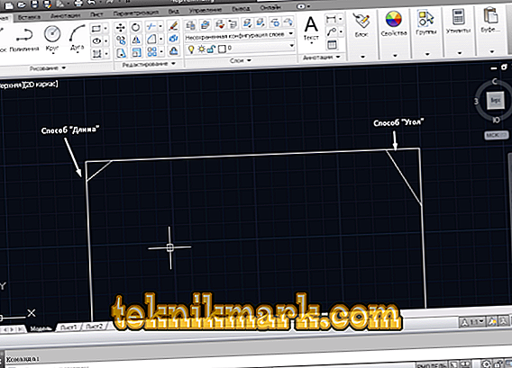
"Chamfer" is a surface formed by beveling the edges of the material. In simple terms, this is a cut angle between two straight lines. It is found everywhere, in engineering, in furniture production and in other areas. So, it is necessary to highlight 2 ways how you can make a chamfer in AutoCAD - this is the length and angle (the distances are taken on two sides from the base.

Method 1
Call the “BACKGROUND” or open the Home tab, the Editing panel - the “Conjugation / Chamfer / Curve Connection” block.

The command line will display the message
And do the following:
- Choose the option “Length”, the program will provide the request “First length” - enter the value required for you (for example, 3/10 // 100) and press “Enter”, by the same principle, set the value for the second length.
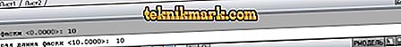
Select chamfer length in Autocad
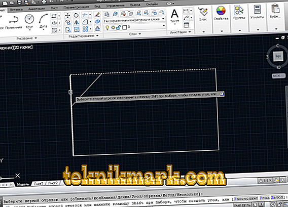
- The initial message will be returned. Now, using the mouse, click on the first segment, the marked segment will be highlighted or italicized.
- Next, move the cursor to the second side, and if everything was done correctly, the program will show what the shape will look like after applying the command, if everything suits, click the second side with the mouse.


Method 2
By the same principle as described above, activate the "FRAME", but instead of the "Length" option, specify "Angle".
- Specify in the request the value of the first length, in the second - the angle in degrees and press "Enter".
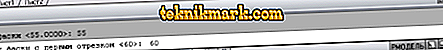
The first chamfer angle
- And again, by analogy with the first described method, mark the first and second segment, as a result, get the cut sides according to the specified parameters.

Both the first and second options have been described using the “Trimming” suboption.
Now you should pay attention to the “Without trimming” suboption:
- After calling the command, click on the button “Trimming”, after opening two options will be offered: “With trimming” and “Without trimming”, respectively, select the second.
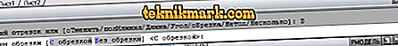
Trim option
- Next, select one of the “Length” or “Angle” methods suitable for you and apply it on the shape.
- As you can see, the “No Cut” chamfer is an independent primitive object (segment) and can be edited separately from the main figure.


Automatic cut of all corners of polylines
A polyline is a representative of complex primitives, which consists of several connected rectilinear and / or arc segments that represent a single object.
Call the command and in the opened request select “polyline”.

It remains only to hover the cursor on a closed polyline, in this case a rectangle, and click on one of the sides of the shape.
Error "Segments are not coplanar"
If, when you try to use the command, the error “Segments are not coplanar” appears, then one of the vertices is not at the same level with the others.
To resolve the error, do the following:
- Mark all lines to be changed and call the "Property".
- For the "Start Z" and "End Z" parameters, set the value to "0".
Useful commands and variables
- “COUNTING” - for rounding edges;
- "RECTANGLE" - to build a closed polyline in the form of a rectangle;
- "CHAMFERA" / "CHAMFERB" - to set the first and second distances;
- "CHAMFERC" - setting the length;
- "CHAMFERD" - set the angle;
- "CHAMMODE" - setting the input method;
- “COMMAND PREVIEW” - a preview of the result of the command execution (applicable for “DESTROY”, “EXTEND”, “ENLARGE”, “COPY TO”;
- “LIKE”, “CUT”;
- "OFFSETGAPTYPE" - adjusts the processing of the gap gaps when changing the position of the polyline;
- "FASKAKROMKI" - bevel edges 3D tel.
As mentioned at the beginning of the article, the fields of application of such an element as “FASKA” are incredibly extensive, so the study of all the nuances of its creation and editing should be given maximum time and attention.